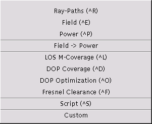
The run menu is used to perform simulation or optimization runs. The computed data can be visualized through the view menu.

Depending on the command performed, certain temporary files are generated and stored into the temporary directory path.
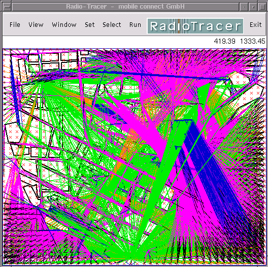
(Shortcut key: Crtl-R). Computes all ray-paths (Fermat paths) according to the settings in the interaction dialog. Previously, the environment, the transmitter(s), and the receiver(s) must be specified. Drawing of ray-paths can be enabled via the set preferences dialog (see the Color Menu for possible user settings of the colors).
Example of a ray-paths drawing:

(Shortcut key: Crtl-E). Computes the complex field of all ray-paths (Fermat paths) according to the settings in the interaction dialog. Previously, the environment, the transmitter(s), and the receiver(s) including their antenna parameters must be specified. Drawing of ray-paths can be enabled via the set preferences dialog (see the Color Menu for possible user settings of the colors).
The output data of the field simulation run can be visualized directly through the point-to-point view menu or the data is used as input data for the Run Power command.
(Shortcut key: Crtl-P). Computes the received power at the receiver locations provided a field simulation run has been performed previously. The following dialog box allows to change the receiver antenna parameters for the power calculation.

The type of antenna can be chosen from the list and its parameters with a subsequent dialog through the [Antenna Setup] button. See the antenna setup dialog for a general description of the antenna settings.
The output data of the power calculation run can be visualized directly through the point-to-multi view menu.
(Shortcut key: Crtl-L). Computes a multi-line-of-sight coverage map, i.e, for each receiver the number of transmitters visible with direct line-of-sight is computed (detailed description).. Previously, the environment, the transmitter(s), and the receiver(s) must be specified. The receiver must be of type area or region, respectively.
Drawing of ray-paths can be enabled via the set preferences dialog (see the Color Menu for possible user settings of the colors). The LOS M-Coverage map can be visualized with the View LOS M-Coverage command.
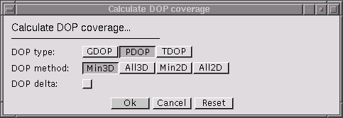
(Shortcut key: Crtl-D). Computes a DOP (dilution-of-precision) coverage map, i.e, for each receiver the DOP value corresponding to the direction vectors towards the directly visible transmitters--depending on the method--is computed (detailed description).. Previously, the environment, the transmitter(s), and the receiver(s) must be specified. The receiver must be of type area or region, respectively.

Specifies the type of DOP to be computed:
Specifies the method how the directional vectors are to be selected:
Drawing of ray-paths can be enabled via the set preferences dialog (see the Color Menu for possible user settings of the colors). The DOP Coverage map can be visualized with the View DOP Coverage command.
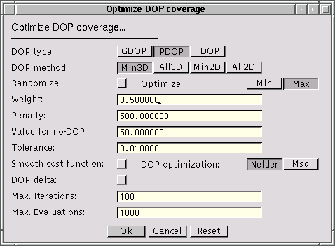
(Shortcut key: Crtl-O). Computes an optimized DOP (dilution-of-precision) coverage map optimizing the locations of the transmitters that are of type area (detailed description). Previously, the environment, the transmitter(s), and the receiver(s) must be specified. The receiver must be of type area or region, respectively. At least one transmitter must be of type area.

Specifies the type of DOP to be computed:
Specifies the method how the directional vectors are to be selected:
Specifies whether the optimization is started with random transmitter locations. If the flag is not set, two consecutive optimization runs performed with the same initial values of the environment, the receivers, and the transmitters will yield the same final result.
Specifies whether the minimum DOP value or the maximum DOP value should be minimized.
Specifies the weight w used in the cost function in the optimization procedure. The value must be in the range [0.0 .. 1.0].
Specifies the penalty p used in the cost function in the optimization procedure. The value must be positive.
Specifies the value to be used for receiver locations where no DOP value can be calculated. If the value is negative, for these points the maximum DOP value of all receiver location is used.
Specifies the tolerance used to determine whether the optimization procedure has been terminated. The value must be positive.
Specifies whether the cost function is smoothed applying a logarithm. A smoother cost function might result in a better convergence of the optimization procedure.
Selects the optimization method: NelderMead or MSD.
Specifies whether delta-DOP or normal DOP should be computed. If delta-DOP is enabled, setting TDOP makes no sense.
Specifies how many iterations are to be performed at most.
Specifies how many evaluations of the cost function (i.e., computations of DOP coverage maps) are to be performed at most.
Drawing of ray-paths can be enabled via the set preferences dialog (see the Color Menu for possible user settings of the colors). The resulting optimized DOP coverage map can be visualized with the View DOP Coverage command.
(Shortcut key: F). Computes a Fresnel clearance coverage map, i.e, for each receiver the clearance percentage of the n-th Fresnel-zone towards the directly visible transmitters is computed (detailed description).. Previously, the environment, the transmitter(s), and the receiver(s) must be specified. The receiver must be of type area.

Specifies the number of the Fresnel-zone for which the coverage should be calculated.
(Shortcut key: Crtl-S). Runs a script file. First, the file is checked syntactically. Incorrect script files are rejected. See the script file format for a formal description of the script file content. If a command in the script file fails (e.g., a configuration file could not be loaded), processing of the script is terminated. Note that commands being executed earlier to the failing one will have effect.
The file name is entered through the file select dialog. The selected file name is maintained and will be presented in a subsequent script command as initial dialog value.
Depending on the version of RadioTracer, certain simulation runs can be executed. See the description of the customized version.