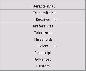
The menu set is used to configure all settings of RadioTracer during an interactive session. The actual configuration can be stored completely or partially through the Store Configuration command. Instead of setting the parameters interactively, configuration files can be loaded through the Load Configuration command.

(Shortcut key: i). The interactions dialog allows to set all relevant data for the ray-path search algorithm, i.e., which types of ray-paths an to which length the ray-paths are search for.
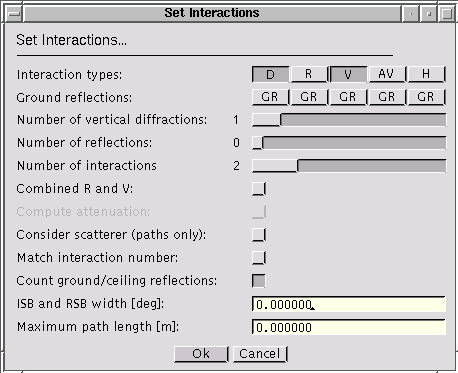
Search for ray-paths with at most that many vertical diffractions. Note, that actually the minimum of Number of Vertical Diffractions and Number of Interactions is used to determine the maximum ray-path length. The value must be positive.
Search for ray-paths with at most that many reflections. Note, that actually the minimum of Number of Reflections and Number of Interactions is used to determine the maximum ray-path length. The value must be positive.
Search for ray-paths with at most that many interactions. This is especially useful to confine the ray-path length when combined reflection and diffraction is set. The value must be positive.
The flag specifies whether to search for ray-paths with both reflections and vertical diffractions. The ray-path length is limited by the Number of Interactions.
The flag specifies whether to compute the distances the ray-paths passes through attenuating media (e.g., trees).
The flag specifies whether to search for ray-paths towards scatterer (e.g., trees). Only first order effects are considered.
The flag specifies whether to search only for ray-paths that match exactly the given Number of Interactions. If this flag is not set, all ray-paths up to the maximum length as given in Number of Interactions are searched for.
The flag specifies whether ground or ceiling reflections are counted as interaction while determining the length of the ray-path. This flag is only used when matching the interaction number is enabled.
Specifies the maximum width of the ISB (incident shadow boundary) and the RSB (reflection shadow boundary) after a vertical diffraction that should be considered during the ray-path search. A value of 0.0 means no limitation of the boundary, i.e., all ray-paths are searched for. The value must be positive, the angle is entered in [deg].
Specifies the maximum length of a ray-paths that should be considered during the ray-path search. A value of 0.0 means no limitation of the length, i.e., all ray-paths are searched for. The value must be positive, the length is entered in [m].
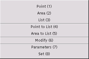
(Shortcut key: 1). Allows to sets a single transmitter as a point. The height of the transmitter is set to the value as specified in the Parameter Settings. The operation can be aborted with a right mouse button click.
(Shortcut key: 2). Allows to sets a single transmitter as a rectangular area. The actual location of the transmitter is computed as the center of the area. The height of the transmitter is set to the value as specified in the Parameter Settings. The operation can be aborted with a right mouse button click.
(Shortcut key: 3). Allows to set a list of transmitters. The transmitters are entered as the corners of a polyline. The polyline is displayed during the interaction. The height of the transmitters is set to the value as specified in the Parameter Settings. The input is finished with a right mouse button click or the operation can be aborted with a right mouse button click before the first point is entered.
(Shortcut key: 4). Allows to add a single transmitter as a point to the list of transmitters. The operation can be aborted with a right mouse button click.
(Shortcut key: 5). Allows to add a single transmitter as a rectangular area to the list of transmitters. The operation can be aborted with a right mouse button click.
(Shortcut key: 6). Allows to modify or to delete the selected transmitter. If currently no transmitter is selected, a selection is requested. In that case, the operation can be aborted with a right mouse button click.
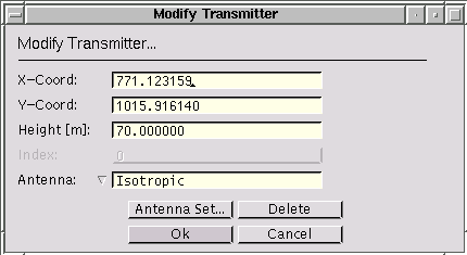
Sets the new location of the transmitter in coordinates of the environment.
Sets the new rectangular area of the transmitter in coordinates of the environment. These entries are only available if the selected transmitter is of type area. Note that it is not forbidden to place the actual location of the transmitter outside the area.
Sets the new height of the transmitter. The height must be larger than 0.0, the value is entered in [m].
Allows to change the antenna. The type of antenna can be chosen from the list and its parameters with a subsequent dialog through the [Antenna Setup] button. See the antenna setup dialog for a general description of the antenna settings. Note that once the antenna has been changed through the antenna setup dialog, the modification is valid even if the dialog is left through the [Cancel] button.
(Shortcut key: 7). Sets the default parameters used during placement of the transmitter with mouse cursor input.

Sets the height in for interactive placement of the transmitter. The height must be larger than 0.0, the value is entered in [m].
Allows to select the default antenna for interactive placement of the transmitter. The type of antenna can be chosen from the list and its parameters with a subsequent dialog through the [Antenna Setup] button. See the antenna setup dialog for a general description of the antenna settings.
(Shortcut key: 8). Allows to set a single transmitter or to add the transmitter to the list of transmitters.
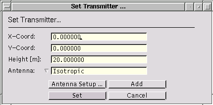
Specifies the location of the transmitter in coordinates of the environment.
Sets the height of the transmitter position. The height must be larger than 0.0, the value is entered in [m].
Allows to select the antenna for the transmitter. The type of antenna can be chosen from the list and its parameters with a subsequent dialog through the [Antenna Setup] button. See the antenna setup dialog for a general description of the antenna settings.

(Shortcut key: .). Allows to set a single receiver as a point. The height of the receiver is set to the value as specified in the Parameter Settings. The operation can be aborted with a right mouse button click.
(Shortcut key: t). Allows to set the receiver as a trajectory (polyline). The height of the receiver points along the trajectory and the sampling rate for the trajectory are set to the values as specified in the Parameter Settings. The input is finished with a right mouse button click. The operation can be aborted with a right mouse button click before the second input point is entered.
(Shortcut key: a). Allows to set the receiver as a rectangular area by specifying two opposite corners. The operation can be aborted with a right mouse button click before the second input point or in the subsequent dialog box.
In the subsequently displayed dialog box the additional parameters are set (see Modify).
(Shortcut key: r). Allows to set the receiver as a region defined as a simple polygon. If the entered polygon is not simple, no receiver samples are taken. The operation can be aborted with a right mouse button click before the second input point or in the subsequent dialog box.
In the subsequently displayed dialog box the additional parameters are set (see Modify).
(Shortcut key: m). Depending on the current receiver type one of the following dialog boxes is presented which allows to modify the receiver parameters.
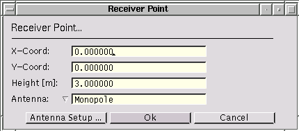
Specifies the location of the receiver in coordinates of the environment.
Sets the height of the receiver position. The height must be larger than 0.0, the value is entered in [m].
Allows to select the antenna for the receiver. The type of antenna can be chosen from the list and its parameters with a subsequent dialog through the [Antenna Setup] button. See the antenna setup dialog for a general description of the antenna settings.
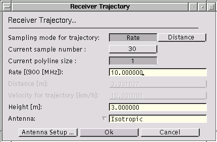
Allows to choose between different sampling modes for interactive placement of the receiver. The trajectory can either be sampled according to the frequency of the default transmitter, or according to a specified distance. Depending on the current selection, the corresponding entries to enter the values are enabled or disabled, respectively. On opening the dialog box, the rate value and the distance value represent the same sampling of the trajectory.
Shows the number of samples on the current trajectory. No value can be entered.
Shows the number of segments of the polyline of the current trajectory. No value can be entered.
Sets the sampling rate in wavelengths of the frequency of the default transmitter. The current frequency is shown within the parentheses. The sampling rate must be larger than 0.0.
Sets the sampling distance in [m]. The sampling distance must be larger than 0.0.
Sets the velocity the receiver moves along the trajectory. The velocity must be different from 0.0, the value is entered in [km/h].
Sets the height of the trajectory. The height must be larger than 0.0, the value is entered in [m].
Allows to select the antenna for the receiver. The type of antenna can be chosen from the list and its parameters with a subsequent dialog through the [Antenna Setup] button. See the antenna setup dialog for a general description of the antenna settings.

Sets the minimum and maximum bounds of the area.
Sets the number of sampling points in x-direction for the area or region.
Sets the number of sampling points in y-direction for the area or region.
Sets the height for the receivers in the area or region. The height must be larger than 0.0, the value is entered in [m].
Specifies whether the height of a receiver point is taken as an absolute value or as a relative value which is added to the current height of the environment at the position of the point.
Allows to select the antenna for the receiver. The type of antenna can be chosen from the list and its parameters with a subsequent dialog through the [Antenna Setup] button. See the antenna setup dialog for a general description of the antenna settings.
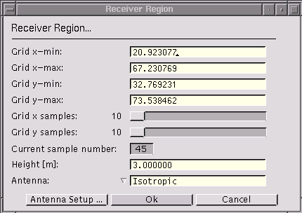
Sets the minimum and maximum bounds of the region. All samples that fall outside of the polygon are not considered as valid receiver points.
Sets the number of sampling points in x-direction for the region.
Sets the number of sampling points in y-direction for the region.
Shows the number of sampling points of the grid that fall into the region.
Sets the height for the receivers in the area or region. The height must be larger than 0.0, the value is entered in [m].
Allows to select the antenna for the receiver. The type of antenna can be chosen from the list and its parameters with a subsequent dialog through the [Antenna Setup] button. See the antenna setup dialog for a general description of the antenna settings.
(Shortcut key: p). The dialog box is used to set certain parameters which are taken as default values for interactive receiver placement.
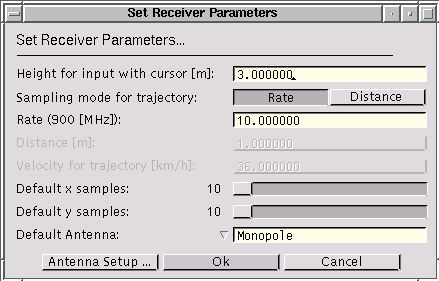
Sets the height for interactive placement of the receiver. The height must be larger than 0.0, the value is entered in [m].
Allows to choose between different sampling modes for interactive placement of the receiver. The trajectory can either be sampled according to the frequency of the default transmitter, or according to a specified distance. Depending on the current selection, the corresponding entries to enter the values are enabled or disabled, respectively. On opening the dialog box, the rate value and the distance value represent the same sampling of the trajectory.
Sets the sampling rate in wavelengths of the frequency of the default transmitter. The current frequency is shown within the parentheses. The sampling rate must be larger than 0.0.
Sets the sampling distance in [m]. The sampling distance must be larger than 0.0.
Sets the velocity the receiver moves along the trajectory. The velocity must be different from 0.0, the value is entered in [km/h].
Sets the default number of sample points in x-direction to be used for interactive placement of the receiver as a grid, region, or area.
Sets the default number of sample points in y-direction to be used for interactive placement of the receiver as a grid, region, or area.
Allows to select the default antenna for interactive placement of the receiver. The type of antenna can be chosen from the list and its parameters with a subsequent dialog through the [Antenna Setup] button. See the antenna setup dialog for a general description of the antenna settings.
Allows to set a receiver directly through a dialog box, which is similar to the one presented in the modify dialog box.
The antenna setup dialog is not directly accessible in the set menu. However, an antenna can be set in various places, so the dialog is described only once in this section.
Several theoretical antenna radiation patterns or measured antenna patterns, which are loaded from a file, can be selected. Setting receiver antennae do not require to set the power. However, the frequency must be set for a receiver antenna as well, because it is needed to determine some geometric parameters of a certain antenna types. The description below refers to setting transmitter antennae. In the case of receiver antennae, certain parameters as indicated below may not be present in the dialog box.

Sets the frequency of the antenna in [MHz].
Sets the input power of the antenna in [W]. The radiated power is calculated as the product of the input power and the efficiency.
Sets the efficiency of the antenna. The value is entered dimensionless. The radiated power is calculated as the product of the input power and the efficiency. (In case of a receiver antenna, the output power is calculated as the product of the received power and the efficiency.)
The isotropic antenna can be polarised either as vertical, or as horizontal, or as left circular, or as right circular.
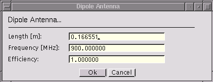
Sets the length of the dipole in [m].
Sets the frequency of the antenna in [MHz].
Sets the input power of the antenna in [W]. The radiated power is calculated as the product of the input power and the efficiency.
Sets the efficiency of the antenna. The value is entered dimensionless. The radiated power is calculated as the product of the input power and the efficiency. (In case of a receiver antenna, the output power is calculated as the product of the received power and the efficiency.)
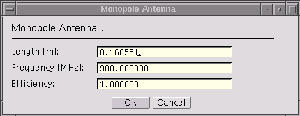
Sets the length of the monopole in [m].
Sets the frequency of the antenna in [MHz].
Sets the input power of the antenna in [W]. The radiated power is calculated as the product of the input power and the efficiency.
Sets the efficiency of the antenna. The value is entered dimensionless. The radiated power is calculated as the product of the input power and the efficiency. (In case of a receiver antenna, the output power is calculated as the product of the received power and the efficiency.)
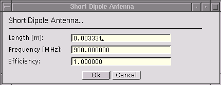
Sets the length of the short dipole in [m].
Sets the frequency of the antenna in [MHz].
Sets the input power of the antenna in [W]. The radiated power is calculated as the product of the input power and the efficiency.
Sets the efficiency of the antenna. The value is entered dimensionless. The radiated power is calculated as the product of the input power and the efficiency. (In case of a receiver antenna, the output power is calculated as the product of the received power and the efficiency.)
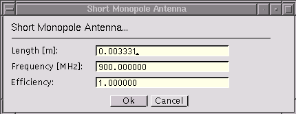
Sets the length of the short monopole in [m].
Sets the frequency of the antenna in [MHz].
Sets the input power of the antenna in [W]. The radiated power is calculated as the product of the input power and the efficiency.
Sets the efficiency of the antenna. The value is entered dimensionless. The radiated power is calculated as the product of the input power and the efficiency. (In case of a receiver antenna, the output power is calculated as the product of the received power and the efficiency.)
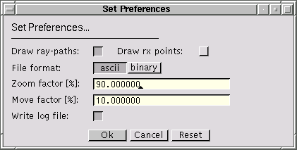
Specifies whether the ray-paths should be drawn during the simulation.
Specifies whether complex receivers should be drawn as set of points of as geometric shapes (polylines or polygons). Note that the currently selected receiver is only marked if the receiver locations are drawn as points.
Specifies whether the output files should be written in BINARY or in ASCII format. Configuration files, script files and material data files are always stored in ASCII format.
Specifies the zoom factor to be used while zooming in or out in the main window. The value must be in the range [1.0 .. 100.0].
Specifies the factor to be used while moving the content of the main window with cursor keys (scrolling). The value must be in the range [0.0 .. 100.0].
Sets whether a log file should be written. Such a log file contains certain error and warning messages that are not presented interactively to the user. The file name is entered through the file select dialog. RadioTracer does not overwrite an existing log file. If the file already exists, the new output is appended. Note that the first and the last entry written to the log file indicate when the log file was opened or closed respectively.
Sets certain tolerances which are used in the computational parts of RadioTracer. The tolerance settings are part of a complete configuration file.

Sets the minimum length of an edge in the environment such that the edge is considered in the ray-path search. The length must not be negative, the value is entered in [m].
Sets the minimum height a diffraction point must have such that the point is considered in the ray-path search. The height must not be negative, the value is entered in [m].
Sets the minimum height a reflection point must have such that the point is considered in the ray-path search. The height must not be negative, the value is entered in [m].
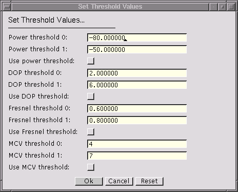
Sets the minimum power a receiver must receive. Any value below the threshold will be clamped to this value. The value is merely used in the plots and maps to avoid practically unrealistic received power values. The value is entered in [dBm].
Sets the number of decimal digits used to write floating point values in ASCII output files.
Sets the threshold values which are used as default values during the visualization of coverage maps of RadioTracer. The thresholds settings are part of a complete configuration file.
Sets the colors to be used in the drawings. The color settings are part of a complete configuration file. Note that the first entry specifies the transparent color, i.e., the object is drawn invisible.

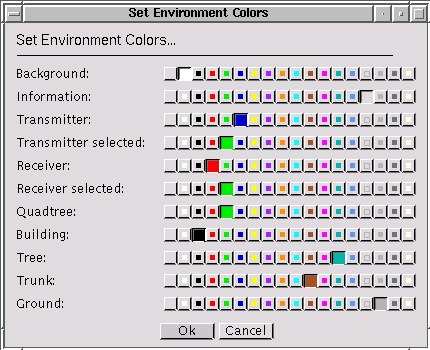
(Shortcut key: c). Sets the different colors for drawings of the environment. Note that the chosen colors will have effect in all windows as well as in the PostScript files.

Sets the different colors for drawings of the ray-paths if this drawing mode is enabled (see set preferences ).
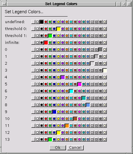
Sets the different colors of the legends used in the maps. The leftmost color representing the smallest value is always the one labelled undefined, the rightmost color representing the largest value is always the one labelled infinite. Note that the chosen colors will have effect in all windows as well as in the PostScript files.
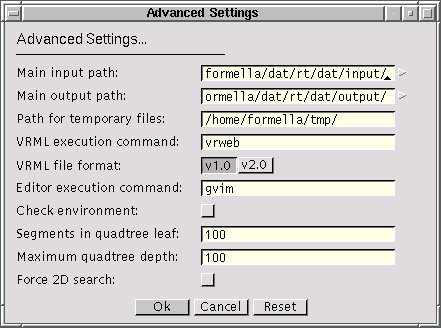
Specifies the directory from where the input files, i.e., the environment, the configuration, the material, and the scripts are taken by default. Only a name of a directory that exists is accepted.
Specifies the directory to where the output files, e.g., the ray-paths, the electromagnetic data, etc. are written by default. Only a name of a directory that exists is accepted.
Specifies the directory to where the temporary files are written. Only a name of a directory that exists is accepted.
Specifies the command line to be used to start the VRML viewer. The viewer visualizes the environment and the ray-paths in three-dimensional mode. (The option is only available with the VRML-package of RadioTracer.)
Selects the VRML format to be standard version 1.0 or standard version 2.0. (The option is only available with the VRML-package of RadioTracer.)
Specifies the command line to be used to start the text editor which will be used for editing text files.
Examples for a possible command line within a Unix environment are
  gvim
  xterm -e vi
Specifies whether a consistency check of the geometric data in the environment is to be performed each time a new environment is loaded. Once a file has been checked, it is convenient to switch-off the possibly time-consuming check whenever the same file is loaded again. The check environment flag is not stored into the configuration file.
If the check finds touching buildings, warning messages are printed to the controlling shell including the points where the buildings touch. If the check finds crossing segments (partially overlapping buildings), a warning message indicating the first intersection point encountered is printed to the controlling shell. The environment will not be loaded if two buildings partially overlap and the check is enabled.
Sets the maximum number of segments that should be contained in a leaf of the quadtree. The value must be at least 4. Note that the construction of the quadtree is terminated as well when the maximum depth has been reached. The setting becomes effective for the next environment to be loaded.
Sets the maximum depths of the quadtree. The value must be positive. A value of 0 means that no quadtree is built. The setting becomes effective for the next environment to be loaded.
Specifies whether the ray-path search should be performed only two-dimensional, i.e., ray-paths over building blocks will not be detected. This mode is especially useful for micro-cell simulations where all building blocks close to the transmitter and the receiver are higher than the antennae heights. RadioTracer switches automatically to the two-dimensional search mode when all building blocks are higher than both the receiver and the transmitter antenna.
Depending on the version of RadioTracer, certain parameters can be set here. See the description of the customized version for more details.